Networking and Communications
This week’s assignment was to design, build, and connect wired or wireless node(s) with network or bus addresses.
This week assignment divided into 2 sections, the first part was during the quarantine period where I had to work with the lab kits, including Arduino and bread board and jumping wires. And the second part was the work in my final project.
LAB Kit
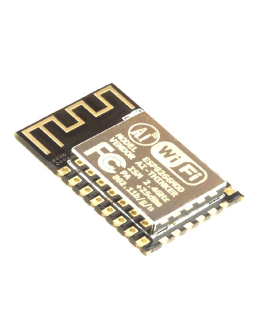
I decided to use the ESP8266 12E module, for the WIFI connection with Arduino. It is used for establishing a wireless network connection for microcontroller or processor.
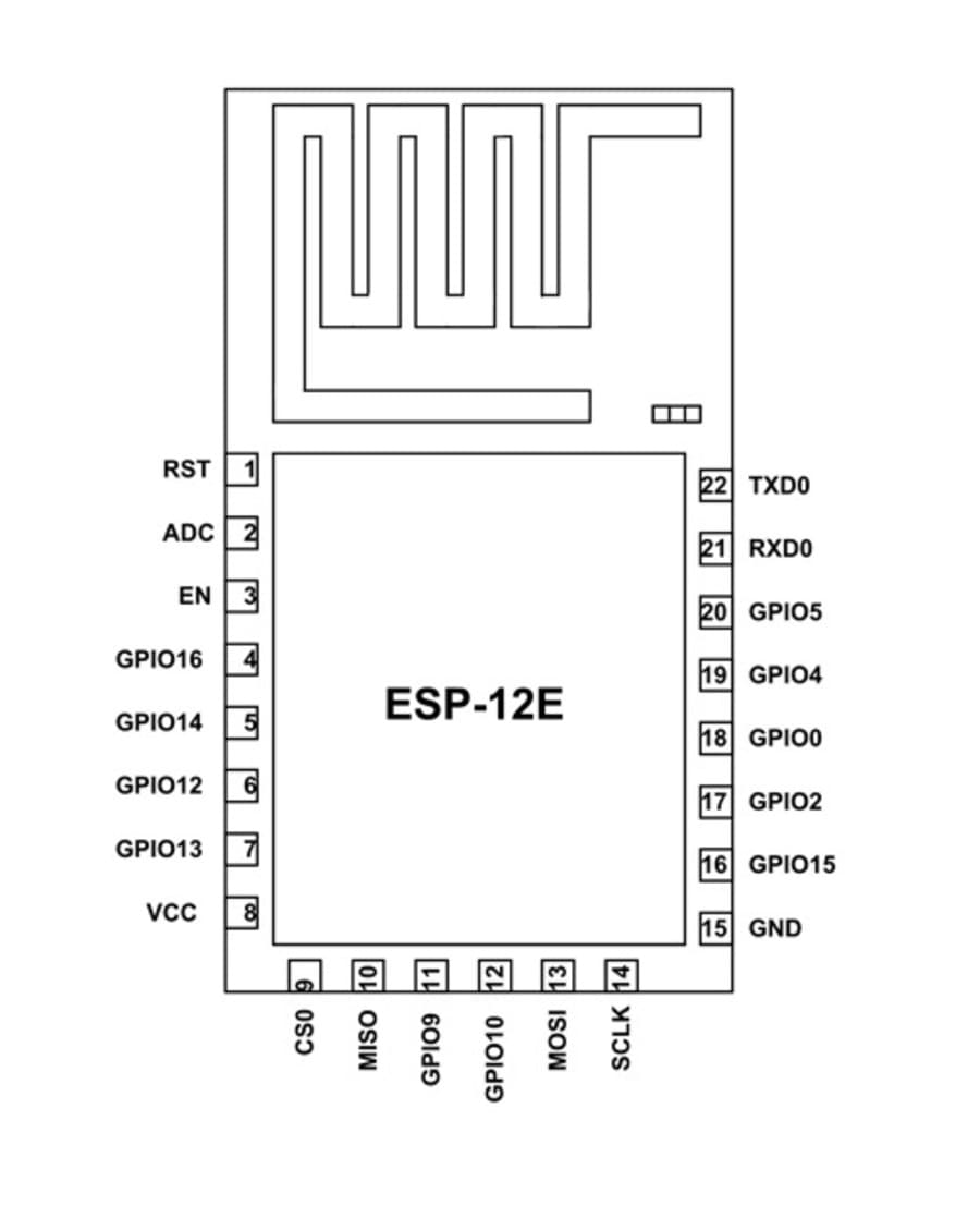
I used its pinout image to know how to connect it with the Arduino, and from the table in the datasheet that shows each pin from the module how should be connected.
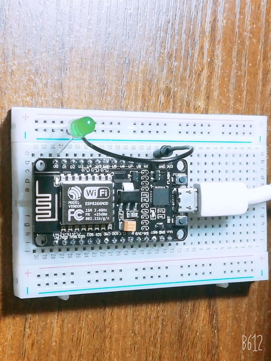
In the bread board, I connected the ESP to it and added the LED as shown below.
In the Arduino IDE, I wrote a program that allows to me to light the LED when on and off. The code first connects your board to the local wifi ( givin its address ad password), and the creates a web page to allow you to control the LED. And from the Serial Monitor it prints out the connection informations, and gives you the IP address for the web page to open it and control your LED.
Arduino Code
const int ledPin = 13;
int incomingByte;
void setup() {
// initialize serial communication:
Serial.begin(9600);
// initialize the LED pin as an output:
pinMode(9, OUTPUT);
pinMode(10, OUTPUT);
pinMode(11, OUTPUT);
}

void loop() {
// see if there's incoming serial data:
if (Serial.available() > 0) {
// read the oldest byte in the serial buffer:
incomingByte = Serial.read();
if (incomingByte == '1') {
analogWrite(9,255 );
analogWrite(10,0 );
analogWrite(11,52 );
}

if (incomingByte == '2') {
      digitalWrite(9,0 );
      digitalWrite(10,0 );
      digitalWrite(11,0 );
}
else {
      analogWrite(9,255 );
      analogWrite(10,0 );
      analogWrite(11,52 );
      delay(500);
      digitalWrite(9,0 );
      digitalWrite(10,0 );
      digitalWrite(11,0 );
      delay(500);
      analogWrite(9,255 );
      analogWrite(10,0 );
      analogWrite(11,52 );
  }
}
Final Project Networking
The second step is working with my final project. Since it a decorative object, I wanted it to be connected wireless to my mobile so I could use it any time.
I used Bluetooth instead of Wi-Fi in my final project since it won’t be used while you are far from it. It’s an interactive masterpiece and needs you to be in front of it to see the lights and heir the voices.
The Bluetooth connections are very easy, it have only 4 pins ( RX, TX, VCC, GND). So, in my schematic I connected them to the ATmega328p microcontroller, but considering the switch between the TX and RX pins, so that the transmitter from the pin connected to receiver from the microcontroller and vice versa.
In the Final Project Tracking page, I explained the whole design process of the board, and the code I used to program it, and you can find videos of the map working while it hanged on the wall.